The S-1 is currently for sale at $495 with $40 shipping and handling to all 50 U.S. states.
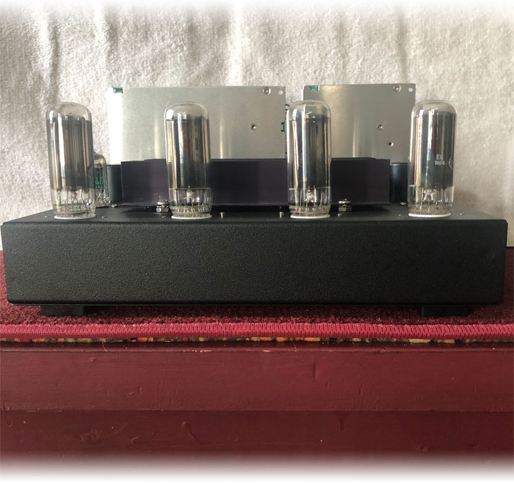
Model S - 1 Description
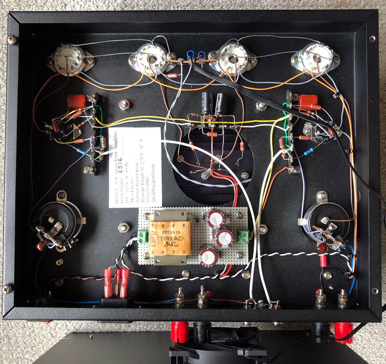
Circuit Description: The input signal is amplified with a conventional two stage voltage amplifier circuit using a 5814 / 6189 / 12AU7 vacuum tube (V1). The amplified signal is capacitively coupled to the gate of an N channel MOSFET (Exicon ECF10N20). The gate is also supplied with a positive bias via voltage divider R!0, R11. This sets a current of approximately 1 Amp through the MOSFET and vacuum tube diodes V2 and V3 (25CG3). The Source terminal of the MOSFET is connected to the plates of V2 and V3, the cathodes of which are grounded. This results in a unique current load for the audio signal which is coupled to the speaker via a 10,000 mfd capacitor. The feedback is taken from the + speaker terminal and fed via C2 and R9 to the cathode of the first triode input stage to the junction of R4 and R5.
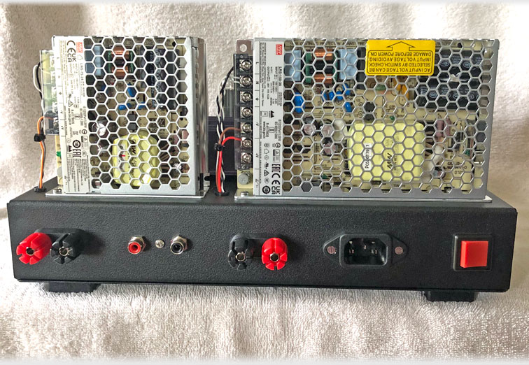
Adjustments: Power Supply PS-1 (Vacuum tube heaters) should be set for 25 VDC
Power Supply PS-2 should be set for 39 VDC Note if you have very efficient speakers,
this voltage may be set lower to 32VDC, this will reduce heat somewhat and prolong V2 and V3 life.
Specifications (Both channels driven)
4 Ω Load: Power output 2 Watts
Damping Factor 22
Input Sensitivity: 3 VRMS
8 Ω Load: Power Output 3 Watts
Damping Factor 41
Input Sensitivity: .5 VRMS
16 Ω Load: Power Output 3 Watts
Damping Factor 86
Input Impedance: 390K
Output Impedance: .18 Ω
Input Sensitivity: 7 VRMS
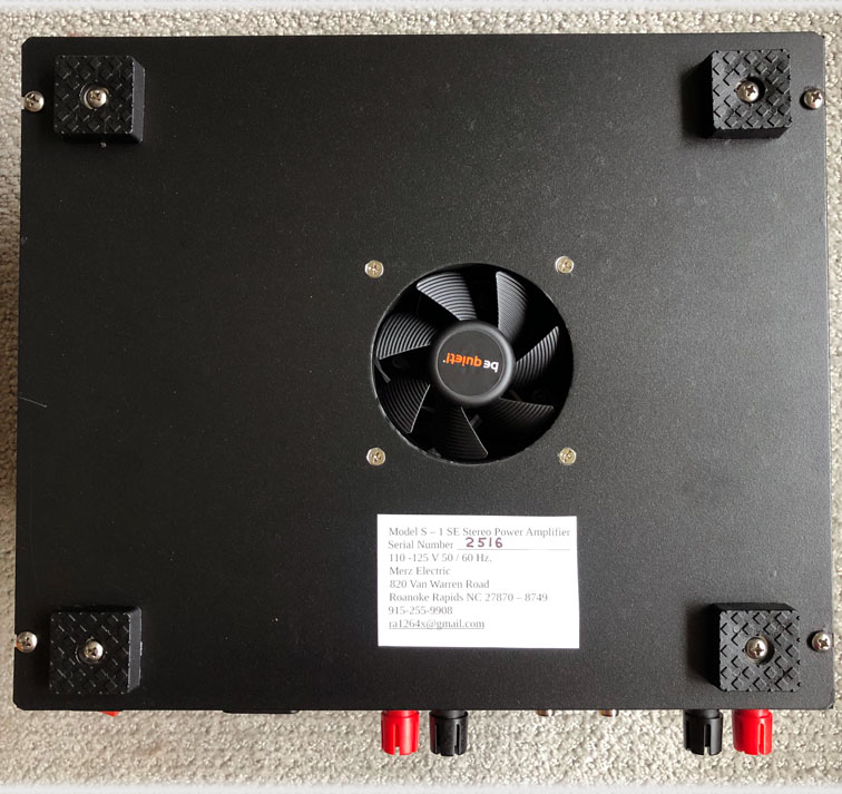
Power 110 - 125 V, 50 / 60 Hz.
Power Consumption: 185 Watts
Dimensions: 12 in W x 10 in D x 6 3/8 in H
Weight: 7.2 Lbs.
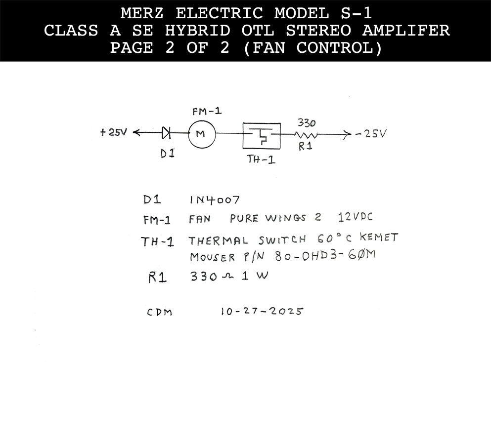
Important Note: This is a Class A type amplifier that produces large amounts of heat. It must have plenty of ventilation and must not be located near any flammable items or where children or pets could come in contact with it.
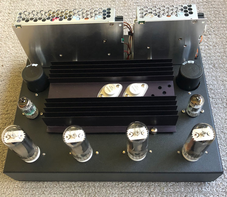
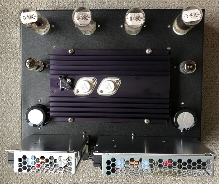
The Circuit and Associated Parts
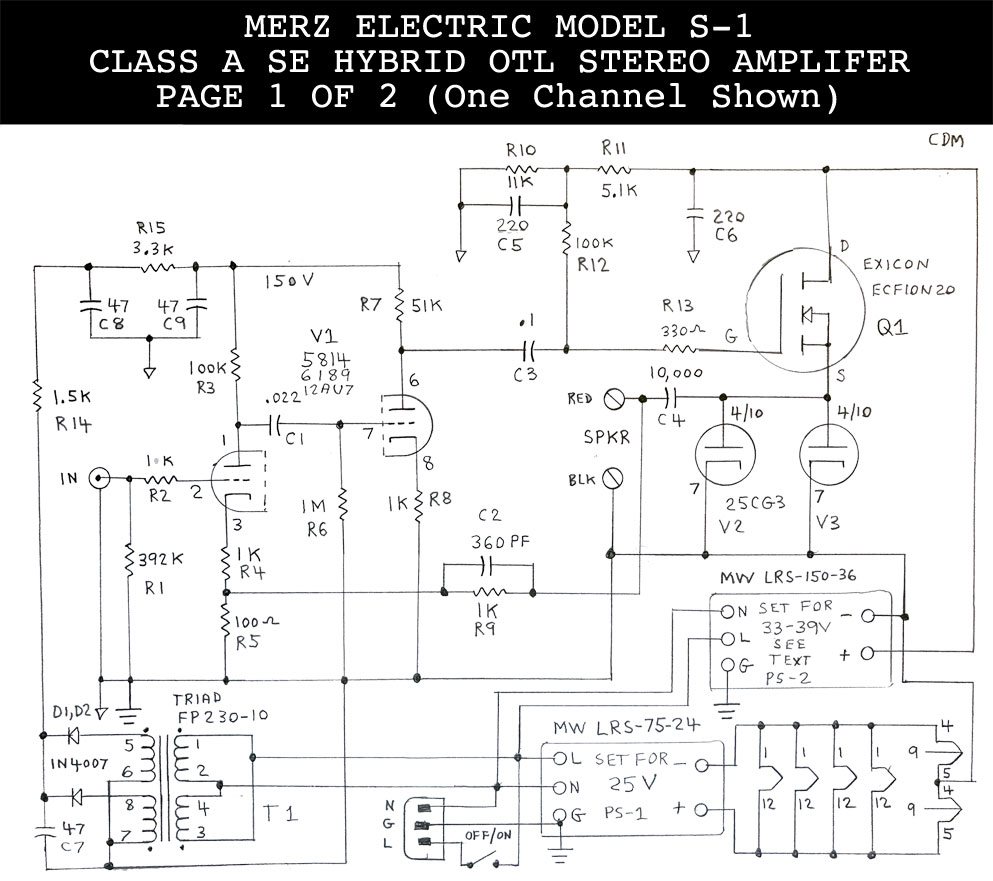
(Click to enlarge)
(Click to enlarge)
Model S - 1 Parts List (One Channel)
C1: .022 mfd 400 V Film
C2: 360 pf 300 V Mica
C3: .1 mfd 630 V Film
C4: 10,000 mfd 63 V Electrolytic 105c C5, C6 220 mfd 63 V Electrolytic 105c
C7, C8, C9: 47 mfd 250 V Electrolytic 105c
D1, D2 : 1N4007 1 Amp, 1000 V
IEC Connector: Various Suppliers
J1, J2: RCA Jack: Keystone 576 (black) 580 (red)
PS1: 24 VDC Power Supply: Mean Well LRS-75-24 PS2, 36 VDC Power Supply: Mean Well LRS-150-36
Q1: MOSFET: Exicon ECF10N20 (N channel)
R1: 392K
R2: 10K
R3 - R12: 100K
R4, R8, R9: 1K
R5: 100 Ω
R6: 1 Meg
R7: 51K
R10: 11K
R11: 5.1K
R13: 330 Ω
R14: 1.5K
R15: 3.3K
S1: Power Switch (6 A, 125 V, Various Suppliers)
ST1: Speaker Terminals: Pomona 6883
T1: Power Transformer: Triad FP230-10
V1: 5814, 6189, 12AU7
V2, V3: 25CG3
Note: All Resistors are ½ Watt, 1%
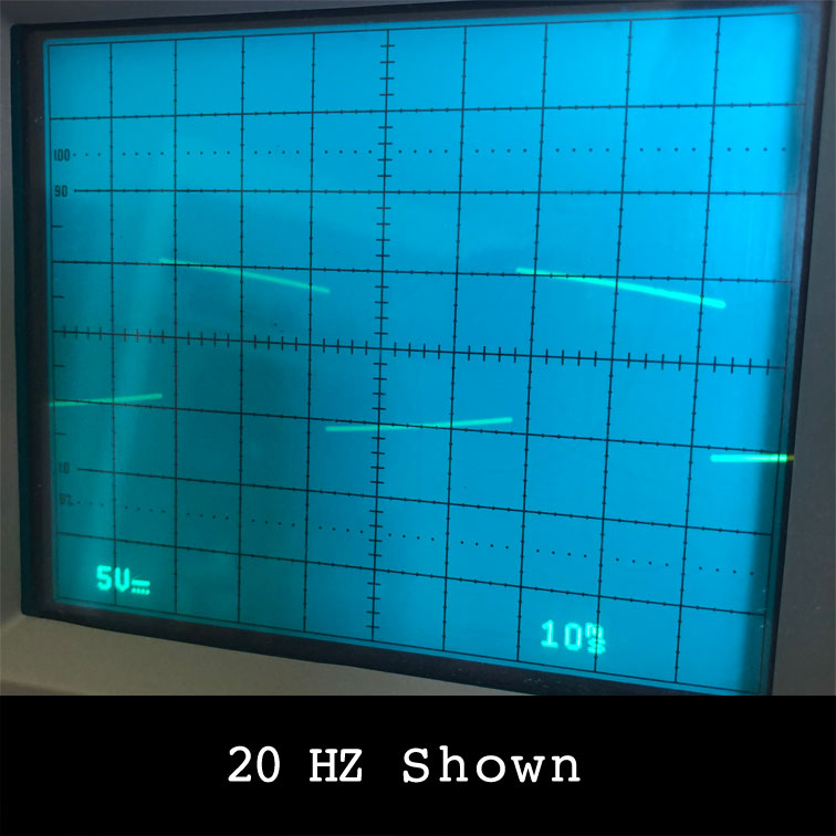
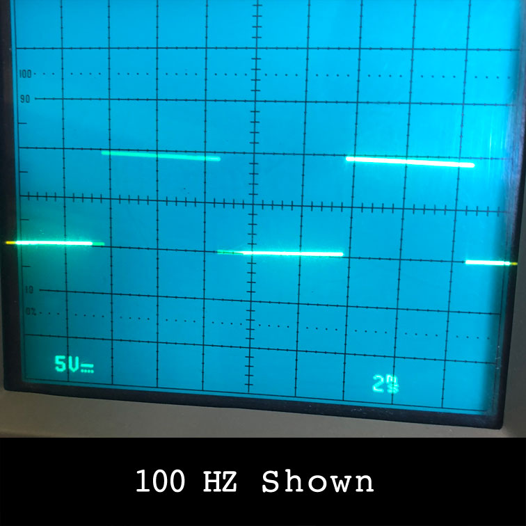
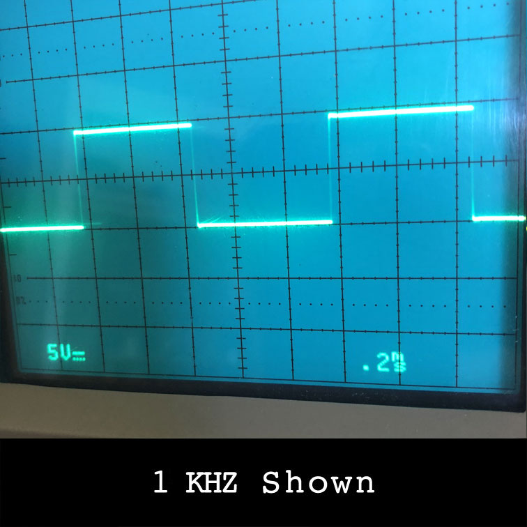
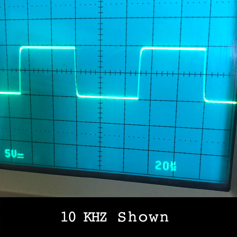
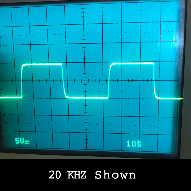
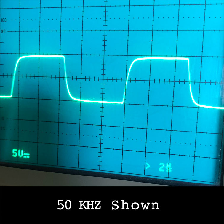
The Square Waves
Square wave photos don’t capture the full picture, but they provide a useful indication of how flat the amplifier’s response is. As you can see, the performance is quite good across the entire range, from 10 Hz to 50 kHz.
This is a direct-coupled amplifier, which typically performs better than transformer-coupled designs, particularly at the extreme low and high frequencies, where transformers have limitations.
While square wave performance doesn’t directly reflect how the amplifier will sound, it does suggest a wide frequency response and minimal "ringing."
For clarity, one channel is shown here, though both channels were driven during the test.
Contact & Sales
Copyright © All rights reserved | Merz Electric