BUILD THIS!
This page is dedicated to hobbyist looking to tackle a more involved project of building a HiFi amplifier.
BUILD This! The “GUTLESS WONDER” Model GW
Here described is a simple construction project that may be ideal for the beginning audiophile who is
interested in building their own audio equipment?
This design uses very few, inexpensive parts and requires minimal chassis drilling. This is not a “kit” so it
does require some basic knowledge of electricity and the use of common hand tools.
The amp is Class AB and is efficient and cool running, a “summer” amp, if you will, that adds little load to the home A/C system. It produces a solid 8 Watts per channel into an 8Ω Load. Changing two resistor values and adding a bodacious heat sink(s) easily converts it to Class A operation
with a power output of about 2 Watts per channel. It may also be made vacuum tube driven (a hybrid
design) which we plan to describe in the future.
Specifications (both channels driven)
Power Output: 4 Ω Load, 9 Watts / 8 Ω, 8 Watts / 16 Ω, 4 Watts (limited by the power supply voltage)
Damping Factor: 4Ω, 50 / 8Ω, 100 / 16Ω, 200
Input Sensitivity (VRMS) 4Ω, .75 / 8Ω, 1 / 16Ω, 1
Input Impedance: 221 K
Output Impedance: .08Ω
Feedback db: 18
Power Requirement: 100 – 240 V 50 / 60 Hz.
Power Consumption: No Signal, 30 Watts / Full Power Output, 60 Watts
Dimensions: 10” D x 12” W x 3 5/8 H
Weight: 3 Lbs.
Circuit Description
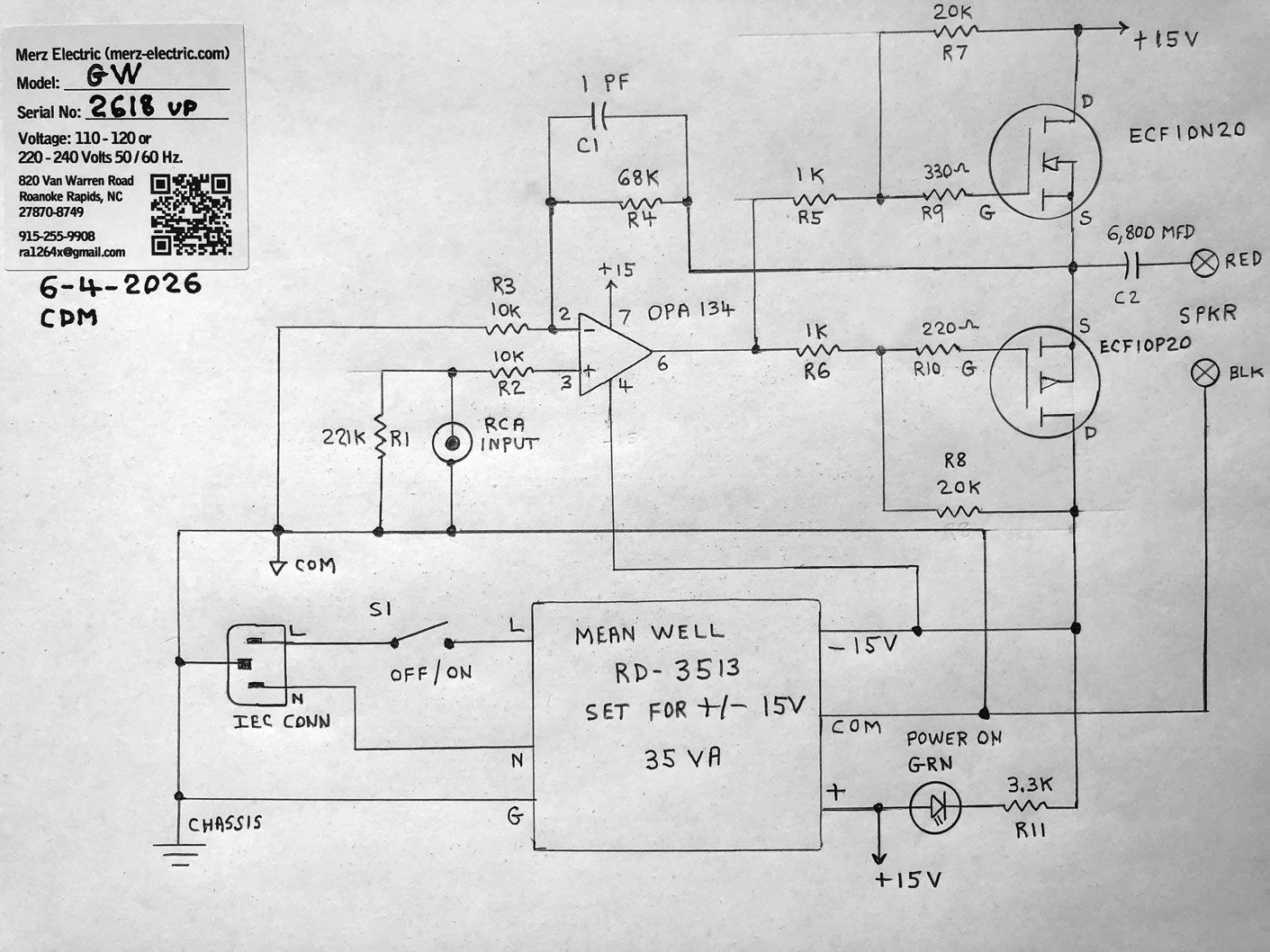
The signal input is coupled directly to the high impedance (pin 3) input to the OPA 134 high slewing
operational amplifier which is wired in the non-inverting configuration with a gain of about 7.8
The ouput of the OPA 134 (pin 6) is fed to the junction of R5, R6 and then to the gates of the two N and P
channel MOSFETS via parisitic suppression resistors R9, R10.
Idle current bias is set via the voltage divider string formed by R5, R6, R7, and R8. This current is in the
range of 50 to 100 mA and is high enough to prevent crossover distortion without producing an excess
amount of heat. The amplifier output is taken the source pins of the two P – P (push-pull) MOSFETS and
is coupled to the speaker via coupling capacitor C2. Overall feedback is taken from the MOSFET source
pins via R4 to the operational amplifier – input (pin 2) Capacitor C1 cleans up minor peaks in the square
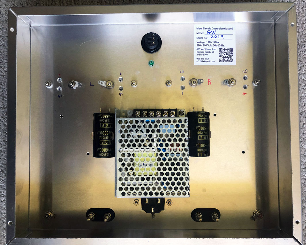
wave performance, which is excellent over the frequency range of 20 Hz. To 100 kHz. The power supply
for both channels is from the 35 VA switching power supply that is set for an output of +/- 15 VDC (the
adjustment potentiometer on the power supply is set full clockwise)
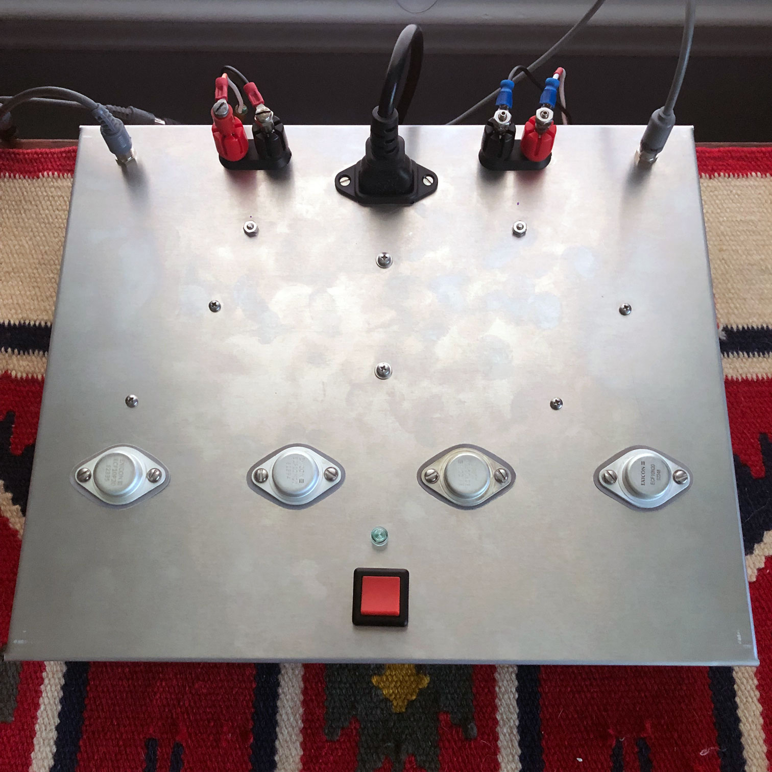
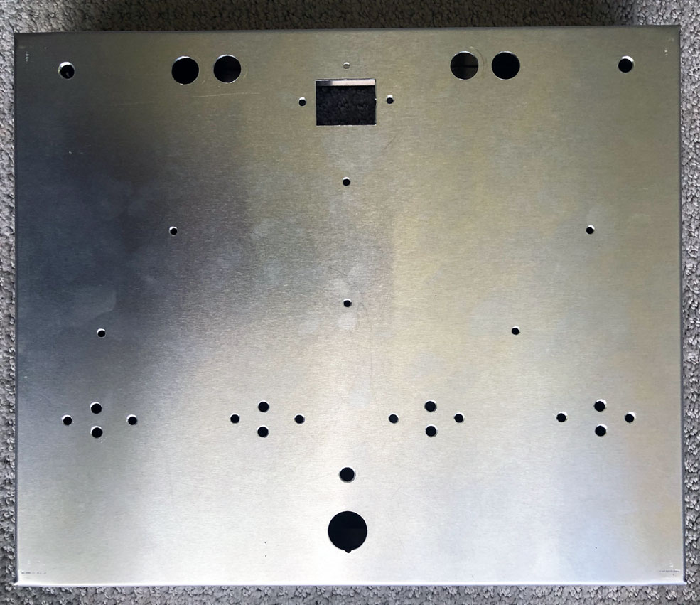
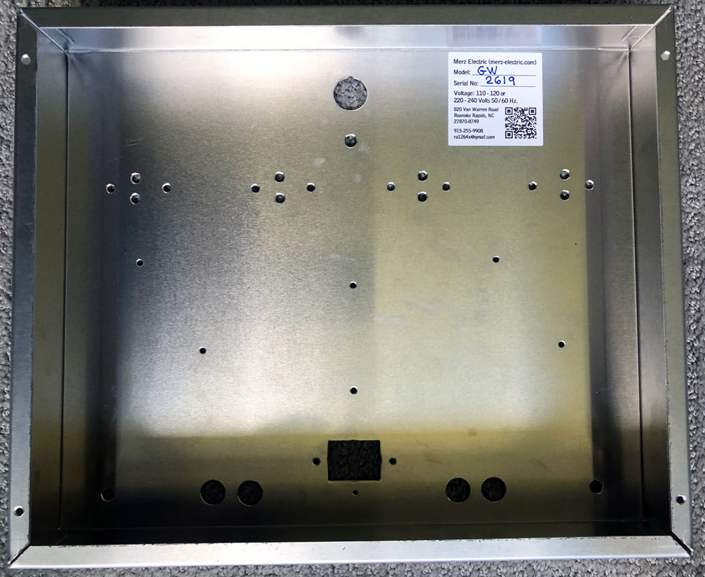
Construction Notes
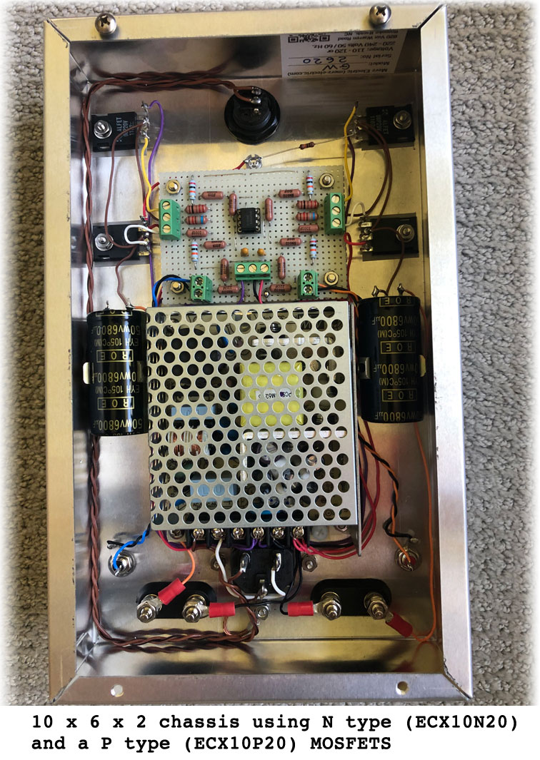
The sample is built on a 10 x 12 x 2 inch aluminum chassis, this provides more than sufficient heat
sinking. If desired, it could be built on a smaller chassis, if one is experienced in working in tighter spaces
but the sample has ample space and will make wiring easier for the hobbyist
.
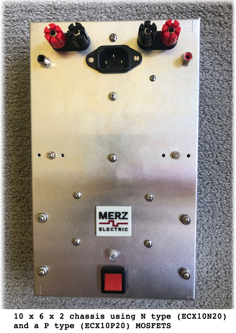
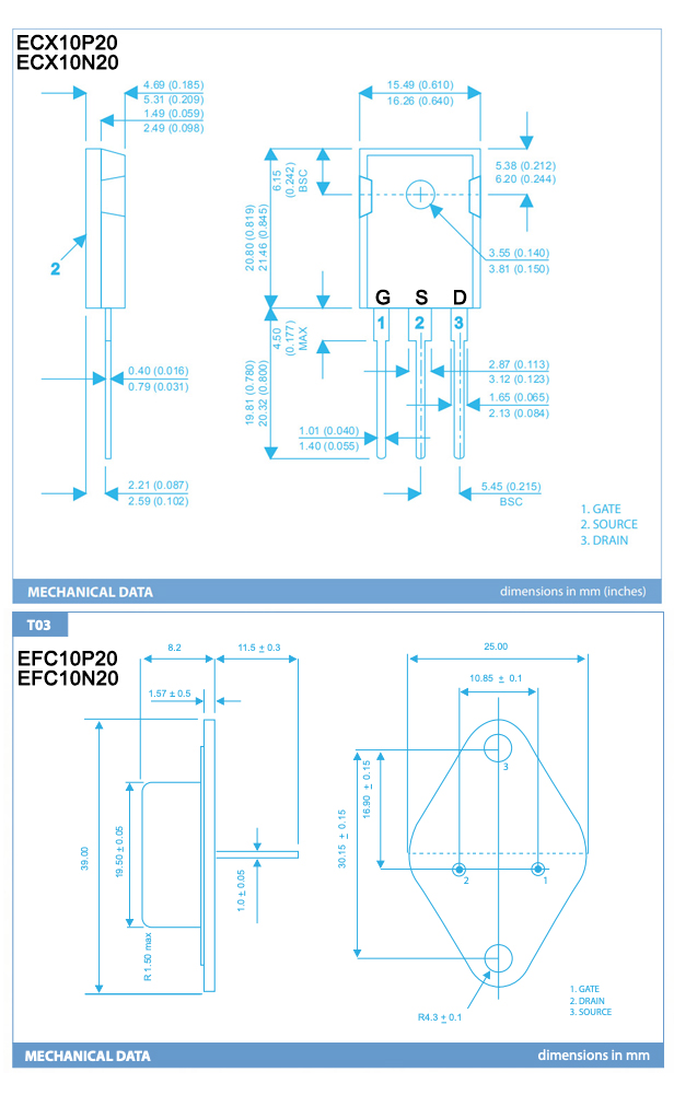
The sample uses the TO-3 case Exicon MOSFETS, the ECF10N20 and ECF10P20. However, Exicon has
stopped making these TO-3 case parts, therefore, it may be easier to obtain the plastic packaged parts, the
ECX10N20 and ECX10P20. It probably makes more sense for the hobbyist to source these parts online
because of the high shipping cost of ordering them directly from the U.K.
The plastic case parts are easier to mount, requiring only one screw, if used, they should be mounted
underneath the chassis. In either case, metal or plastic, the devices must be insulated from the metal
chassis. If the metal TO-3 part is used, the insulator may be used as a template, as these holes need to be
quite accurate. After mounting the MOSFETS, use a DMM to check that they are not grounded to the
chassis or to each other.
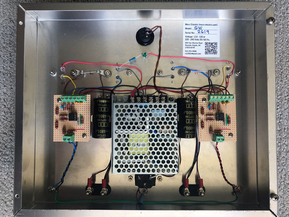
Once mounted to the chassis, the power supply case will be grounded to the chassis and the ground screw is not needed.
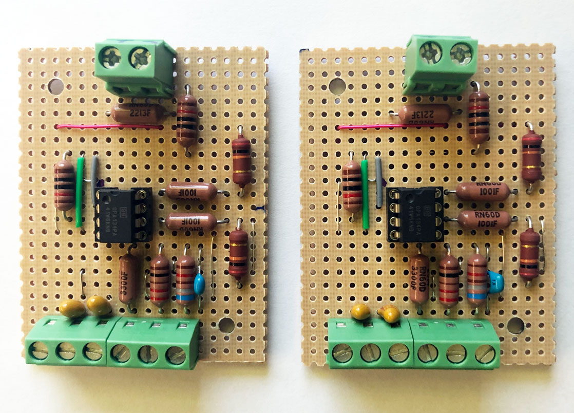
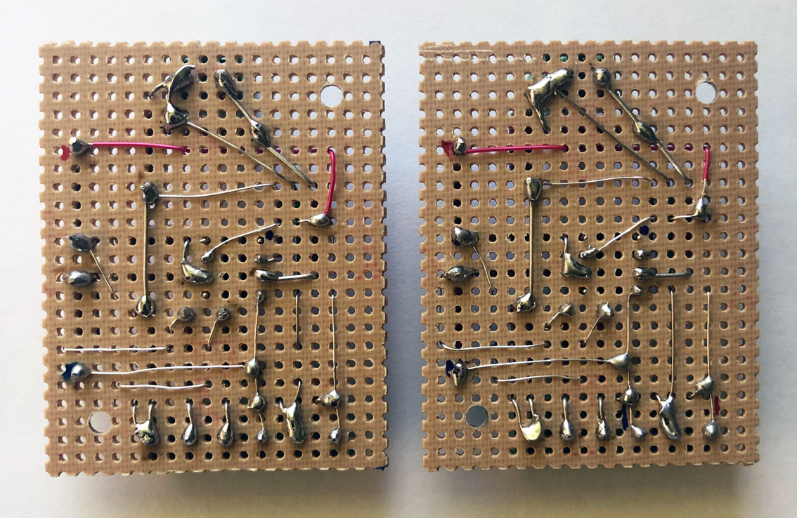
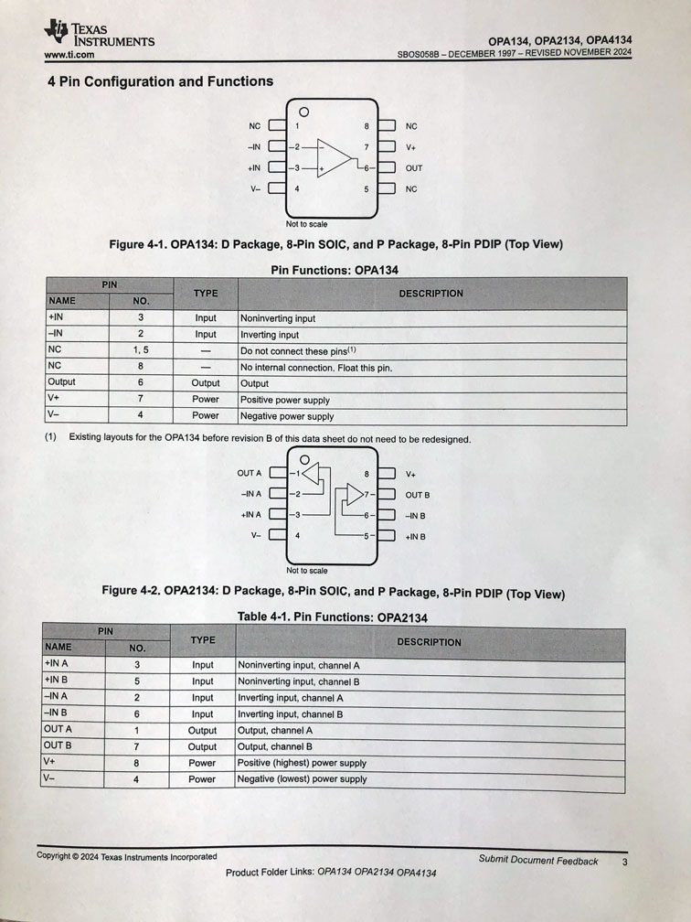
Because the circuit is simple, it is easily fabricated on perforated board material. Layout is not critical but a small tipped soldering iron works best, especially when soldering to the operational amplifier pins. It’s best to use an 8 pin DIP socket for the IC rather than soldering directly to the OPA 134 pins. Use thin wire, not over 26 or 24 AWG. 28 or 30 AWG Kynar wire-wrap wire works well for the IC socket pins.
The grounding sequence for each channel is best as follows: Power supply COM to speaker (black) terminal then to “C” terminal on the circuit board. Next from “C” terminal at input to RCA jack shield then to the chassis ground near the IEC connector. Note: The RCA jacks are grounded when mounted, so it’s not absolutely necessary to run a ground wire to the chassis connector.
Output coupling capacitor C2 should be at least 6800 mfd but may be as large as 10,000 mfd. Larger values will extend the low frequency response below 20 Hz. But its often desirable to start rolling off below 20 Hz. to minimize subsonic noise.
The currents in the circuit is low, so 22 AWG solid Teflon insulated wire was used in the sample. Teflon is easier to work with when soldering, since it’s high temperature insulation resists “burnback” Teflon is more difficult to strip but a pair of standard “Miller” type strippers work well (available at Lowes or Home Depot) “Squeeze” type strippers will not work unless they have Teflon dies installed. Of course, other types of wire may be used.
The sample shows two circuit boards, one for each channel, however with a different layout, the dual OPA 2134 may be used with both channels built on a single circuit board. The bottom plate may be attached with either No. 8 sheet metal screws or tapped for 8-32 machine screws. In either case, the screws should not be tightened to much, since the soft aluminum is easily stripped out, just snug.
Other than the 120 to 240 V AC power input, there are no other dangerous voltages involved.
Enjoy this construction project ! Careful workmanship will give good results.
cdm 6-5- 2026
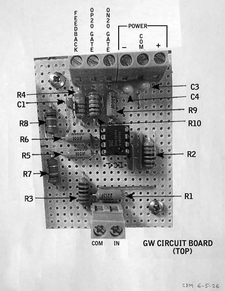
The Circuit and Associated Parts
(Click to enlarge)
(Click to enlarge)
(Click to enlarge)
(Click to enlarge)
Model GW Parts List for both channels (see construction notes) Mouser part numbers, unless noted otherwise.
C1: 1 pf mica 300 V 2ea. PN: 59B-CD5CC010D03F
C2: 6800 mfd 35 V electrolytic 85 or 105 C 2ea. PN: 667-EEU-HD1V682
C3, C4 : 1 mfd 35 V Tantalum 4ea. PN: 80-T350A105M035AT
Q1: N Channel MOSFET Exicon ECF10N20 (TO-3) or ECX 10N20 (Plastic) 2ea.
Q2: P Channel MOSFET Exicon ECF10P20 or (TO-3) ECX10N20 (Plastic) 2ea.
Note: The Plastic parts are suggested for ease of mounting and because the TO-3 case is being obsoleted. Order from profusion.uk or find on eBay, etc.
IC 1: TI OPA 134PA 2ea. Or OPA-2134 (dual) lea. 595-OPA134PA (single) or 595-OPA2134 (dual)
LED 1: Standard Green LED with Clear Lens Cap 1ea. 604-WP483GDT Lens Cap 534-8665
P1: Standard IEC Power Connector 1ea. PN: 562-703W-00/02
Power Supply: MeanWell RD-3513, 35 VA, +/- 13.5 V (Adjust to +/- 15 V) 1ea. PN: 709-RD13
R1: 221K 2ea. PN: 71-RN60D2213F/R
R2, R3: 10K 4ea. PN: 71-RN60D1002F/R
R4: 68K 2ea. PN: 71-RN60D6802F
R5, R6: 1K 4ea. PN: 71-RN60D-F-1.0K
R7, R8: 20K 4ea. PN: 71-RN60D2002FRE6
R9: 330Ω 2ea. PN: 71-RN60D3300F
R10: 220Ω 2ea. PN: 71-RN60D2200FB14
R11: 3.3K 1ea. PN: 71-RN60D3301F
S1: Power Switch, 6A 125V / 3A 250V PN: aretronics.com RS-144 / RS-145 or as desired.
TO-3: Insulating Pads 4ea. PN: 739-A15036008
Insulating Bushings 8ea. (4ea. If using plastic package parts) PN: 534-7684
TO-247: Insulating Pads 4ea. (If using plastic package parts) PN: 739-A15038105
Black RCA Input Jack, Keystone 534-576 1ea.
Red RCA Input Jack, Keystone 534-582 1ea.
Speaker Terminals, Pomona 6883 2ea. PN: 6883 565-6883
Aluminum Chassis, 10x12x2 Hammond Mfg. 1444-29 1ea. PN: 546-1444-29
Aluminum Bottom Plate, 10x12 Hammond Mfg. 1434-29 1ea. PN: 546-1434-29
Bottom Feet: 4 ea. Surplus Sales of Nebraska FR-33 or as desired.
Misc. #4 Hardware (18-8 stainless steel) eBay or as desired.
Misc. #6 Hardware (18-8 stainless steel) eBay or as desired.
8-32 Machine Screws or Sheet Metal Screws for Bottom Plate 4ea. eBay or as desired.
Perforated Circuit Board Material, Vector 169P99 (paper) or 169P84WE (fiberglass)
4-40 Metal or Nylon Standoffs, 1⁄4” to 1⁄2” high, 4ea. 534-1892
1” Capacitor Mounting Clips, 2ea.
Terminals: 3 Position 4ea. Phoenix or equivalent.
Terminal: 2 Position 2ea. Phoenix or equivalent.
Mise. 22 AWG Teflon Insulated Wire, Solid Source from: apexjr.com
Note: All resistors are 1% 1⁄4 to 1⁄2 Watt Film Type. Vishay CCF60, RN60 or equivalent.
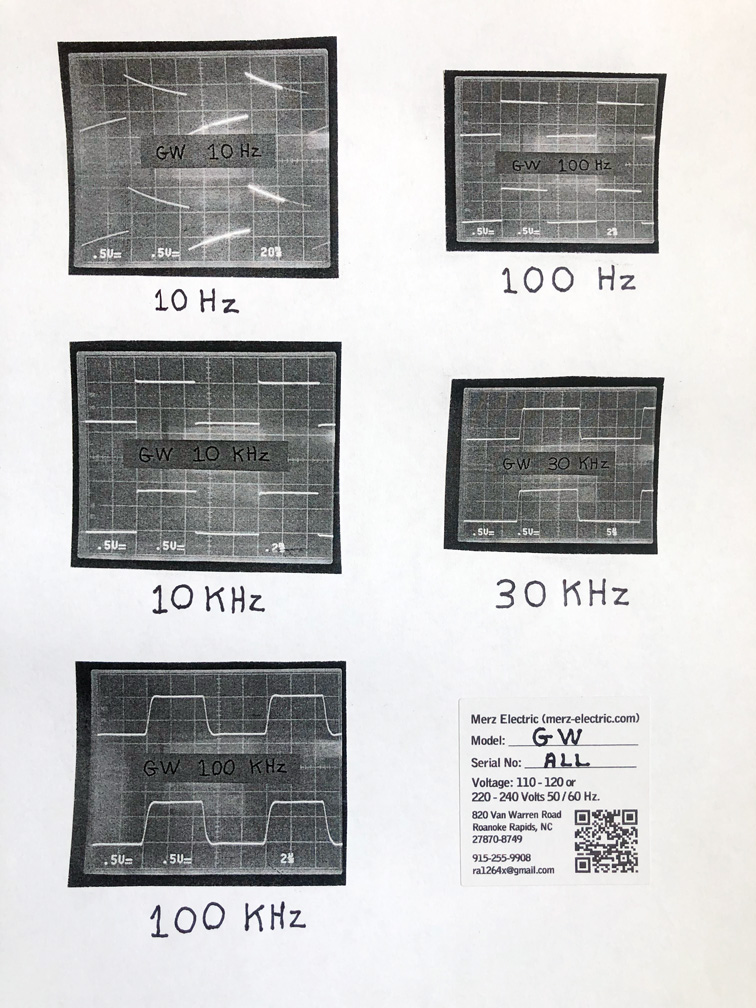
The Square Waves
Square wave photos don’t capture the full picture, but they provide a useful indication of how flat the amplifier’s response is. While square wave performance doesn’t directly reflect how the amplifier will sound, it does suggest a wide frequency response and minimal "ringing."
For clarity, one channel is shown here, though both channels were driven during the test.
(Click to enlarge)
Contact & Sales
Copyright © All rights reserved | Merz Electric